

Hdd Horizontal Drilling lets crews install underground pipes and conduits while keeping the surface largely undisturbed. Instead of opening a continuous trench, a drill rig creates a guided path beneath roads, landscaped areas, or waterways. The method can reduce surface disruption, but it still demands careful planning.
HDD specialist James H. Barritt has written about the method and its field practices. The following is a paraphrase of those practical principles, not a verified verbatim quotation: “A reliable bore depends on planning, steering, and understanding the ground.” That distinction matters. Soil and rock conditions can change over a short distance, and no route behaves perfectly.
A typical installation begins with a planned entry and exit point. The crew drills a small pilot bore, tracking its position with locating equipment. The drill head can be steered to follow the designed alignment. After it reaches the exit, the crew attaches the product pipe and pulls it back through the enlarged bore. Simple in outline. Technical in practice.
This guide explains the equipment, drilling stages, tracking, and site factors that shape an HDD project. It also looks at common limitations, including changing ground conditions and the need to manage drilling fluid. Plans help, but they do not remove uncertainty. A useful explanation should show both what the process can do and where careful judgment remains essential.
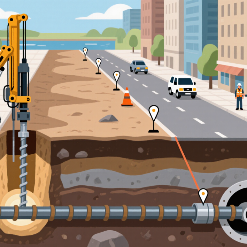
HDD Fundamentals: A Trenchless Method for Installing Underground Utilities
Horizontal directional drilling, or HDD, installs underground pipes and cables with limited surface excavation. It is useful beneath roads, driveways, and landscaped areas where an open trench would cause disruption. A crew drills a small pilot bore along a planned path. A locating system tracks the drill head and helps the operator guide it around obstacles. Ground conditions matter.
After the pilot bore reaches its exit point, the crew may enlarge the hole with a reamer. The utility line is then attached and pulled back through the bore. Drilling fluid helps carry soil cuttings out and supports the bore, but its behavior depends on the soil. Sand, cobbles, and unexpected fill can complicate the work. Plans can be imperfect; careful site checks and ongoing tracking help crews respond before small deviations become costly problems.
Before horizontal directional drilling (HDD), map the bore against actual site conditions, not just a straight line on a screen. Gather available utility records and arrange a field locate to mark buried services. Check entry and exit areas, nearby structures, and clearance at each crossing. Records may be incomplete, so treat them as clues rather than proof. Small details matter.
Ground conditions influence the route and drilling plan. Review geotechnical information for soil layers, rock, groundwater, and possible obstructions. Where information is limited, targeted site investigation can reduce uncertainty. Set the intended alignment with practical depth and bend limits in mind, and confirm that the exit point is accessible for receiving the drill head. A carefully drawn route can still miss local changes in soil; revise it when field evidence calls for a closer look.
Tips: Walk the alignment before work begins. Compare marked utilities with the plan, and pause if locations conflict. Do not guess. Document changes so the crew works from the same, current route.
In HDD horizontal drilling, the bore path bends beneath roads, driveways, or other obstacles. HDPE pipe must follow that path without being forced into a sharper curve than it can safely tolerate. A common planning range for minimum bend radius is 25–40 times the pipe’s outside diameter. For a 110 mm pipe, that suggests roughly 2.75–4.4 m. The exact limit depends on pipe design and installation conditions.
Check the pipe supplier’s guidance before setting the bore profile. SDR, temperature, handling, and pulling loads can all affect allowable curvature. Cold HDPE may be less flexible, while a tight bend can cause kinking or add stress during pullback. Measure it twice. A gentle curve on a drawing may look different in a crowded work area, where entry pits and existing utilities restrict the setup.
Keep the planned radius visible in the drilling layout, and inspect the pipe as it enters the bore. Watch for flattening, scuffing, or a bend that tightens near the entry point. If the route cannot maintain the required radius, adjust the bore path or installation plan rather than forcing the pipe. Field measurements are useful, but they are not a substitute for the pipe’s rated limits. Even careful estimates can miss a constraint. That deserves a second look.
A commonly used planning range for HDPE pipe bend radius is about 25–40 times its outside diameter (OD). The bars show the corresponding radius range for each pipe size. Actual limits depend on pipe specifications, temperature, installation conditions, and project requirements; confirm the permitted bend radius before installation.
The process starts with a steerable drill head that cuts a narrow pilot bore along the planned route. A locator tracks the head’s depth and direction, while the operator adjusts its path around obstacles. Small details matter. A shallow change in pitch can affect where the bore emerges, so crews check tracking readings throughout the drill.
The pilot bore is usually too small for the product pipe. Crews attach a reamer and pull it back through the bore, enlarging the opening; they may repeat this in stages. NASTT’s HDD Good Practices Guidelines describe bore sizing as dependent on ground conditions and product dimensions. A common planning range is about 1.2 to 1.5 times the product’s outside diameter. For a 300 mm pipe, that suggests a bore of roughly 360–450 mm, though the right size depends on soil, fluid circulation, and pullback needs. Not a fixed rule. ASTM F1962-22 also emphasizes designing HDD installations around site conditions and installation forces. In practice, an experienced crew watches for changing torque, poor returns, or unstable ground. These signs can call for a slower reaming pass or a revised plan. Reaming is not just making a larger hole; it is managing the space and support needed for a controlled pullback.
After the pilot bore is enlarged, the product pipe is attached behind a reamer and swivel. The HDD rig then pulls the assembly back through the bore. This is the third core stage, but it is not simply a matter of applying more force. The crew watches pullback force, drilling-fluid returns, and pipe movement throughout the operation. A sudden force increase or a loss of returns can signal trouble underground.
Pipe capacity needs checking before the pull begins. The Plastics Pipe Institute’s Handbook of Polyethylene Pipe explains that allowable pulling load depends on pipe wall area and tensile stress, not diameter alone. For example, a 250 mm outside-diameter pipe at SDR 11 has a nominal wall thickness of about 22.7 mm, before manufacturing tolerances. ASTM F1962 provides an engineering method for estimating pull forces during PE pipe installation by HDD. These calculations help set limits; they do not replace live monitoring.
Keep the pipe clean and supported at the entry pit. The swivel should prevent reamer rotation from twisting the product pipe. Record pull force and fluid returns at regular intervals, then inspect the exposed pipe for scoring, kinks, or damage. Verify the installed route and elevation against the bore plan, and complete the specified pressure or leak test. A smooth pull is reassuring, not proof of a sound installation. That distinction is easy to overlook.

